2.12. Configuring mirror
Overview
Function Introduction
Mirror function can send one or more copies of packets which are passing through the ports/vlans or sending and receiving by CPU to one or more specified destination ports. It can also send the copies to the CPU and keep in memory or flash files.
The copies of the packets are used for network analyze. The mirror function does not affect the original network traffic.
Principle Description
The following describes concepts and terminology associated with mirror configuration:

1.Mirror session
A mirror session is an association of a mirror destination with one or more mirror source. The mirror destination and mirror source will describe later.
The device supports up to 3 mirror sessions.
Mirror sessions do not interfere with the normal operation of the switch. However, an oversubscribed mirror destination, for example, a 10-Gbps port monitoring a 100-Gbps port, results in dropped or lost packets.
2.Mirror direction
The device supports to set the direction of the mirror source, there are 3 options for choose: TX/RX/BOTH.
Receive (RX) mirror: The goal of receive (or ingress) mirror is to monitor as much as possible packets received by the source interface or VLAN before any modification or processing is performed by the switch. A copy of each packet received (except these packets: BPDU, LACPDU, BMGPDU, packets have been discarded by IP-MAC binding check for Vlan_based mirror, CRC error packets for both Port_based and vlan_based mirror) by the source is sent to the destination port for that mirror session. You can monitor a series or range of ingress ports or VLANs in a mirror session. Packets that are modified because of routing are copied without modification; that is, the original packet is copied.
Packets that are modified because of quality of service (QoS)(for example, modified Differentiated Services Code Point (DSCP)) are copied with modification. Packets that are modified because of VLAN translation or VLAN classification is copied with the modification. Some features that can cause a packet to be dropped during receive processing have no effect on mirror, the destination port can receive a copy of the packet even if the actual incoming packet is dropped. These features include ingress ACL, VLAN’s ingress filter, MAC filter, STP, VLAN tag control, port security, unknown routing packets.
Transmit (TX) mirror: The goal of transmit (or egress) mirror is to monitor as much as possible packets sent by the source interface after all modification and processing is performed by the switch. A copy of each packet (except these packets: packets from CPU port for Vlan_based mirror, mirroring packets for both Port_based and vlan_based mirror) sent by the source is sent to the destination port for that mirror session. Some features that can cause a packet to be dropped during transmit processing might have affect on mirror.
Both: In a mirror session, you can monitor a single port for both received and sent packets.
3.Mirror source
The Mirror source is the original traffic of the network. The types of source are described as following:
Source port: A source port is a layer2 or layer 3 interface which need to be monitored. A physical port or link agg port can be a source port. The member of link agg port is not supported to be a mirror source.
Source VLAN: A source vlan is a vlan which need to be monitored. User should create a vlan interface before set a vlan as mirror source.
CPU:User can set CPU as mirror source to monitor the packets send to or receive from the CPU. The copies of packets send to the mirror destination are before cpu-traffic-limit process. Only session 1 support CPU as mirror source currently.
4.Mirror destination
Mirror function will copy the packets and sent the copies to the mirror destination.
The types of destination are described as following:
Local destination port: The destination port should be a physical port or link agg port, member of link agg port is not supported. The destination port has these characteristics:
It must reside on the same switch as the source port.
It should not be in “shutdown” state
It can participate in only one mirror session at a time (a destination port in one mirror session cannot be a destination port for a second mirror session).
It cannot be a source port.
The port does not transmit any traffic except that required for the mirror session.
It does not participate in spanning tree while the mirror session is active.
When it is a destination port, all other normal system function of this port should not work until mirror destination configure disabled on this port.
No address learning occurs on the destination port.
The real statues of the speed/duplex might not coincide with the values which are displayed.
Multi-destination: The device supports to use a group of destination ports to receive several copies of the traffic. The characteristics of each member in the group of destination ports are same as single destination port.
Remote destination A remote mirror destination is a remote destination vlan, which has a specified outgoing port. The copies of the packets should be send to the specified port and add the tag of the remote vlan. A remote destination has these characteristics:
It is a vlan with a specified outgoing port.
The remote VLAN range should be 2 to 4094. If the VLAN isn’t created in system, user can not configure this VLAN as mirror remote vlan.
The outgoing port should be a physical port. User should manually check if the outgoing port can transfer mirrored packets.
Monitor traffic packets are inserted a tag with the remote VLAN ID and directed over the specified outgoing port to the mirror destination session device.
It is recommended to configure remote mirror’s destination port as switch port. Users should add the destination port to the remote vlan otherwise the mirrored packet can not be transmitted out.
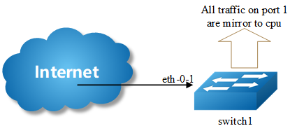
CPU destination send the copies of packet to the CPU of current device. If there is no analyzer available, user can use CPU as mirror destination and save the result for user or developers analyze packets.
You can analyze network traffic passing through ports or vlans by using mirror function to send a copy of the traffic to another port on the switch that has been connected to a Switch Probe device or other Remote Monitoring (RMON) probe or security device. However, when there is no other monitoring device for capturing packets, normal mirror destination to ports doesn’t work. So we can set CPU as mirror destination to send a copy of the traffic to CPU for storing packets. It supports the cli to display the packets of mirror CPU and write the packets in a text file. It is a very functional debug tool. Mirror does not affect the switching of network traffic on source ports or source vlans; a copy of the packets received or sent by the source interfaces are sent to the destination CPU. The cpu-traffic-limit rate can be configured. CPU can participate as a destination in only one mirror session.
Configuration
Configuring Local port mirror

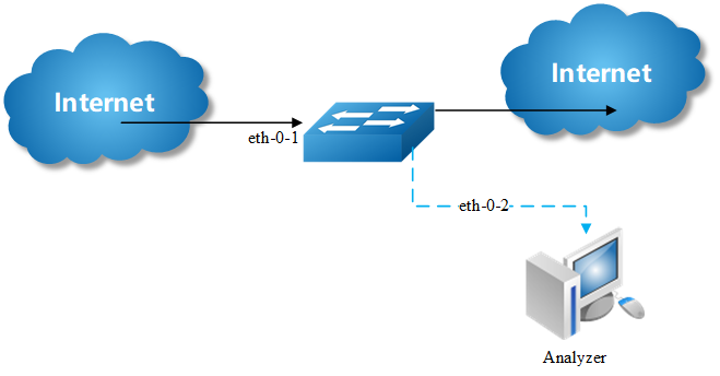
Copy the packets of eth-0-1 and send them to eth-0-2
step 1 Enter the configure mode
Switch# configure terminal
step 2 Set the destination of mirror
Switch(config)# interface eth-0-2
Switch(config-if)# no shutdown
Switch(config-if)# exit
Switch(config)# monitor session 1 destination interface eth-0-2
step 3 Set the source of mirror
Switch(config)# monitor session 1 source interface eth-0-1 both
step 4 Exit the configure mode
Switch(config)# end
step 5 Validation
Switch# show monitor session 1
Session 1
----------
Status : Valid
Type : Local Session
Source Ports :
Receive Only :
Transmit Only :
Both : eth-0-1
Source VLANs :
Receive Only :
Transmit Only :
Both :
Destination Port : eth-0-2
Configuring local vlan mirror
Copy the packets from vlan 10 and send them to eth-0-2.
step 1 Enter the configure mode
Switch# configure terminal
step 2 Set the destination of mirror
Switch(config)# interface eth-0-2
Switch(config-if)# no shutdown
Switch(config-if)# exit
Switch(config)# monitor session 1 destination interface eth-0-2
step 3 Enter the vlan configure mode and create a vlan
Switch(config)# vlan database
Switch(config-vlan)# vlan 10
Switch(config-vlan)# exit
step 4 Create a vlan interface
Switch(config)# interface vlan10
Switch(config-if)# exit
step 5 Set the source of mirror
Switch(config)# monitor session 1 source vlan 10 rx
step 6 Exit the configure mode
Switch(config)# end
step 7 Validation
Switch# show monitor session 1
Session 1
----------
Status : Valid
Type : Local Session
Source Ports :
Receive Only :
Transmit Only :
Both :
Source VLANs :
Receive Only : 10
Transmit Only :
Both :
Destination Port : eth-0-2
Configuring CPU as mirror source
Copy the packets from or to CPU and send them to eth-0-2.
step 1 Enter the configure mode
Switch# configure terminal
step 2 Set the destination of mirror
Switch(config)# interface eth-0-1
Switch(config-if)# no shutdown
Switch(config-if)# exit
Switch(config)# monitor session 1 destination interface eth-0-2
step 3 Set the source of mirror
Switch(config)# monitor session 1 source cpu both
step 4 Exit the configure mode
Switch(config)# end
step 5 Validation
Switch# show monitor session 1
Session 1
----------
Status : Valid
Type : Cpu Session
Source Ports :
Receive Only :
Transmit Only :
Both : cpu
Source VLANs :
Receive Only :
Transmit Only :
Both :
Destination Port :eth-0-1
Configuring Multi-destination Mirror

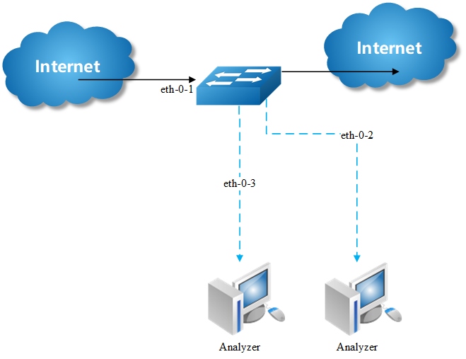
Copy the packets of eth-0-1 and send them to eth-0-2 and eth-0-3
The rules of mirror source are same as single destination port. The following case use source port for example.
step 1 Enter the configure mode
Switch# configure terminal
step 2 Set the destination group of mirror
Switch(config)# interface eth-0-2
Switch(config-if)# no shutdown
Switch(config-if)# exit
Switch(config)# interface eth-0-3
Switch(config-if)# no shutdown
Switch(config-if)# exit
Switch(config)# monitor session 1 destination group 1
Switch(config-monitor-d-group)# member eth-0-2
Switch(config-monitor-d-group)# member eth-0-3
Switch(config-monitor-d-group)# exit
step 3 Set the source of mirror
Switch(config)# interface eth-0-1
Switch(config-if)# no shutdown
Switch(config-if)# exit
Switch(config)# monitor session 1 source interface eth-0-1
step 4 Exit the configure mode
Switch(config)# end
step 5 Validation
Session 1
----------
Status : Valid
Type : Local Session
Source Ports :
Receive Only :
Transmit Only :
Both : eth-0-1
Source VLANs :
Receive Only :
Transmit Only :
Both :
Destination Port : eth-0-2 eth-0-3
Configuring Remote Mirror

If local device cannot connect to an analyzer directly, User can choose remote mirror to send the copies of packets with specified vlan tag.
The remote device can pick out the packets with this vlan for analyze.
The following example copies the packets form Switch1’s eth-0-1, and send them to Switch2 via Switch1’s eth-0-2. Switch2 sends these packets to the analyzer.
The configuration of Switch1:
step 1 Enter the configure mode
Switch# configure terminal
step 2 Set the destination of mirror
Switch(config)# vlan database
Switch(config-vlan)# vlan 15
Switch(config-vlan)# exit
Switch(config-if)# exit
Switch(config)# interface eth-0-2
Switch(config-if)# no shutdown
Switch(config-if)# switchport mode trunk
Switch(config-if)# switchport trunk allowed vlan add 15
Switch(config-if)# exit
Switch(config)# monitor session 1 destination remote vlan 15 interface eth-0-2
step 3 Set the source of mirror
Switch(config)# interface eth-0-1
Switch(config-if)# no shutdown
Switch(config)# monitor session 1 source interface eth-0-1 both
step 4 Exit the configure mode
Switch(config)# end
step 5 Validation
Switch# show monitor session 1
Session 1
----------
Status : Valid
Type : Remote Session
Source Ports :
Receive Only :
Transmit Only :
Both : eth-0-1
Source VLANs :
Receive Only :
Transmit Only :
Both :
Destination Port : eth-0-2
Destination remote VLAN : 15
The configuration of Switch2:
Use these methods on Switch2 to send packets to analyzer via eth-0-2.
method 1: use vlan 15 as mirror source eth-0-2 as mirror destination
Switch# configure terminal
Switch(config)# vlan database
Switch(config-vlan)# vlan 15
Switch(config-vlan)# exit
Switch(config)# interface vlan15
Switch(config-if)# exit
Switch(config)# interface eth-0-2
Switch(config-if)# no shutdown
Switch(config)# interface eth-0-1
Switch(config-if)# no shutdown
Switch(config-if)# switchport mode trunk
Switch(config-if)# switchport trunk allowed vlan add 15
Switch(config-if)# exit
Switch(config)# monitor session 1 destination interface eth-0-2
Switch(config)# monitor session 1 source vlan 15 rx
Switch(config)# end
method 2: add both ports in to the same vlan (15), and make the packet flood in this vlan
Switch# configure terminal
Switch(config)# no spanning-tree enable
Switch(config)# vlan database
Switch(config-vlan)# vlan 15
Switch(config-vlan)# exit
Switch(config)# interface eth-0-2
Switch(config-if)# no shutdown
Switch(config-if)# switchport mode access
Switch(config-if)# switchport access vlan 15
Switch(config)# interface eth-0-1
Switch(config-if)# no shutdown
Switch(config-if)# switchport mode trunk
Switch(config-if)# switchport trunk allowed vlan add 15
Switch(config-if)# exit

Fig. 2.4 configuration VLAN tag is stripped because eth-0-2 is access port.
method 3: flood in vlan and keep vlan tag 15
If user needs to keep the vlan tag 15, eth-0-2 should be trunk port (other configurations are same as method 2):
Switch(config)# interface eth-0-2
Switch(config-if)# no shutdown
Switch(config-if)# switchport mode trunk
Switch(config-if)# switchport trunk allowed vlan add 15
Configuring CPU Mirror Dest

step 1 Enter the configure mode
Switch# configure terminal
step 2 Set the destination of mirror
Switch(config)# monitor session 1 destination cpu
Set the buffer size and to cpu rate:
Switch(config)# monitor cpu set packet buffer 100
Switch(config)# cpu-traffic-limit reason mirror-to-cpu rate 128
step 3 Set the source of mirror
Switch(config)# monitor session 1 source interface eth-0-1 both
step 4 Exit the configure mode
Switch(config)# end
Optional steps
Enable or disable to write the packets in to the flash files.
Switch# monitor cpu capture packet start
Switch# monitor cpu capture packet stop
Exchange the files from *.txt to *.pcap
Switch# pcap convert flash:/mirror/MirCpuPkt-2023-02-05-18-31-13.txt flash:/MirCpuPkt-2023-02-05.pcap
Set the action after the packet buffer is exceeded: drop means discard the latest packet; replace means discard the oldest packet.
Switch(config)# monitor cpu capture strategy drop
Switch(config)# monitor cpu capture strategy replace
step 5 Validation
This example shows how to set up a mirror session, session 1, for monitoring source port traffic to a destination cpu. You can use show monitor session to see the configuration.
Switch# show monitor session 1
Session 1
----------
Status : Valid
Type : Cpu Session
Source Ports :
Receive Only :
Transmit Only :
Both : eth-0-1
Source VLANs :
Receive Only :
Transmit Only :
Both :
Destination Port : cpu
This example shows how to display the mirror cpu packets
Switch# show monitor cpu packet all
-----------------show all mirror to cpu packet info-----------------
packet: 1
Source port: eth-0-1
MACDA:264e.ad52.d800, MACSA:0000.0000.1111
vlan <tag:100>
IPv4 Packet, IP Protocol is 0
IPDA:3.3.3.3, IPSA: 10.0.0.2
Data length: 47
Data:
264e ad52 d800 0000 0000 1111 8100 0064
0800 4500 001d 0001 0000 4000 6ad9 0a00
0002 0303 0303 6365 6e74 6563 796f 75
This example shows how to display the mirror buffer size:
Switch# show monitor cpu packet buffer
--------------------show packet buffer size---------------------
The mirror-to-cpu packet buffer size of user set is: 100
This example shows how to display the mirror cpu traffic-limit rate:
Switch# show cpu traffic-limit | include mirror-to-cpu
mirror-to-cpu 128 0
This example shows how to display the files of the flash:
Switch# ls flash:/mirror
Directory of flash:/mirror
total 8
-rw-r----- 1 2287 Dec 23 01:16 MirCpuPkt-2023-12-23-01-15-54.txt
-rw-r----- 1 2568 Jan 3 11:41 MirCpuPkt-2023-01-03-11-41-33.txt
14.8T bytes total (7.9T bytes free)
Switch# more flash:/mirror/ MirCpuPkt-2023-01-03-11-41-33.txt
sequence srcPort
1        eth-0-1
++++++++1483443444:648884
8c 1d cd 93 51 00 00 00 00 00 11 11 08 00 45 00
00 26 00 01 00 00 40 00 72 d0 01 01 01 01 03 03
03 03 63 65 6e 74 65 63 79 6f 75 63 65 6e 74 65
63 79 6f 75
--------
sequence srcPort
2        eth-0-1
++++++++1483443445:546440
8c 1d cd 93 51 00 00 00 00 00 11 11 08 00 45 00
00 26 00 01 00 00 40 00 72 d0 01 01 01 01 03 03
03 03 63 65 6e 74 65 63 79 6f 75 63 65 6e 74 65
63 79 6f 75
This example shows how to display the files of the flash. *.pcap files can open with packets analyzer applications such as Wireshark. Please referenc to the FTP/TFTP/SCP part to download the files.
Switch# ls flash:/mirror
Directory of flash:/mirror
total 12
-rw-r----- 1 2287 Dec 23 01:16 MirCpuPkt-2023-12-23-01-15-54.txt
-rw-r----- 1 2568 Jan 3 11:41 MirCpuPkt-2023-01-03-11-41-33.txt
-rw-r--r-- 1 704 Jan 3 13:07 test.pcap
14.8T bytes total (7.9T bytes free)
This example shows how to display the actions after the buffer is full
Switch# show monitor cpu capture strategy
The capture strategy of cpu mirror is: replace (add new packet and remove oldests packet when buffer is full)
Application cases
N/A